Load balancer
You only have to configure a load balancer if you plan to set up Work.AI in the high-availability mode. In the case of the Basic installation, ignore this instruction.
Requirements
A hardware load balancer must be provided and configured in advance before installing Work.AI.
The load balancer must have an IP address (Virtual IP, VIP) assigned to which all clients' external connections will be established.
The load balancer must support Layer 4 TCP load balancing.
The load balancer must listen to the specific ports described in the table below. You can override ports in the config file before the installation. The table describes the default port numbers set initially in the config file inside the installation package. If you want to use different ports, make sure that the ports configured to listen on the load balancer are updated accordingly in the configuration file during installation:
Port numbers (default values from ports.yml) Respective setting in ports.yml TCP: 80 lb_port TCP: 443 lb_port_ssl TCP: 7374 kes_proxy_port TCP: 8202 vault_proxy_port The load balancer must route all TCP traffic from the specified ports to the same ports on Master1, Master2, and Master3 servers (simple round-robin balancing between Master1, Master2, and Master3). It means that the ports must be accessible from the load balancer's network interface to all Master1-3 servers' network interfaces.
We recommend configuring the load balancer to perform TCP health checks of the "
lb_port_ssl" port of Master1-3 servers every 5 seconds to check that a server is alive.All load balancer TCP ports from the table above must be accessible over the VIP from every server of the environment.
TLS termination must be disabled on the external load balancer.
Configure load balancer
Select your Load Balancer type:
- Hardware
- AWS
- Azure internal LB
In the load balancer's configuration, specify the following parameters for it:
Configure the list of servers to be balanced:
- Master hostname 01 (for example, master1.example.com)
- Master hostname 02 (for example, master2.example.com)
- Master hostname 03 (for example, master3.example.com)
Create the following list of ports that VIP will listen to (see comment and table above, that these ports may be changed during installation):
- TCP: 80
- TCP: 443
- TCP: 7374
- TCP: 8202
Configure health checks:
- Ports to listen: TCP 443. If the port is unavailable, HAProxy is down.
- Servers in the Target group to check: Master Server hostname 01, Master Server hostname 02, Master Server hostname 03.
- Rules:
- The number of failed health checks to consider the server is down. By default, 3.
- The number of passed checks to consider the server is restored. By default, 1.
- The interval of health checks, by default, 20 seconds.
Set Sticky sessions to the Round Robin mode.
Set Client NAT.
Before creating a Load Balancer, make sure that you understand which connectivity scheme you are going to use:
- Internet-facing: a public IP address is assigned to the customer-facing interface of the balancer. In this case, before creating a load balancer, make sure that you have a free Elastic IP (EIP) address available.
- Internal: a private IP address is assigned to the customer-facing interface of the balancer.
Step 1. Create target groups
A target group is a set of backend servers. In our case, they are two application servers.
Go to https://console.aws.amazon.com/ec2/ to open the Amazon EC2 console.
On the navigation pane, in the Load Balancing section, select Target Groups.
Select Create target group.
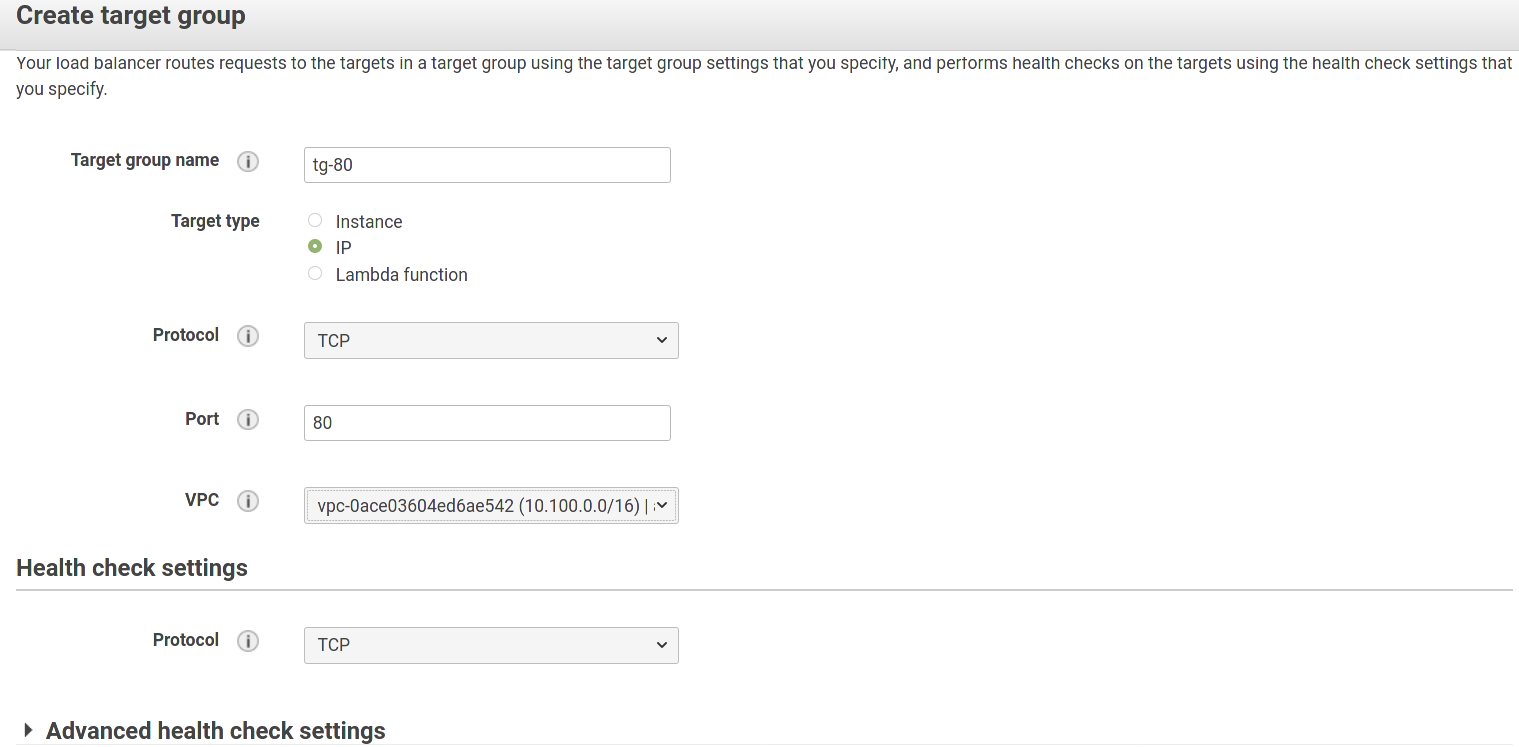
Create three target groups one by one for each port that Load Balancer will listen to. Specify the following parameters:
- Target group name: any meaningful string.
- Target type: IP.
- Protocol (for the target group and health checks): TCP.
- Advanced health check settings: we recommend leaving the settings in this section as is.
Here is an example for port 80:
Step 2. Register targets with target groups
For each of created target group, do the following:
Go to the Targets tab and click Edit.

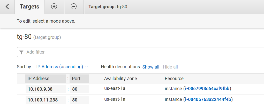
Select the "+" tab at the bottom of the page, fill in the IP of each of two application servers and click Add to list. Then, click the "Register" button. As a result, you will see two servers on the Targets tab at the top of the page:
Click Save.
Step 3: Create a Network Load Balancer and a Listener
- On the navigation pane of the AWS console, in the Load Balancing section, select Load Balancers.
- Select Create Load Balancer.
- For Network Load Balancer, select Create.
Step 4: Configure a Network Load Balancer (NLB)
To create listeners and specify availability zones:
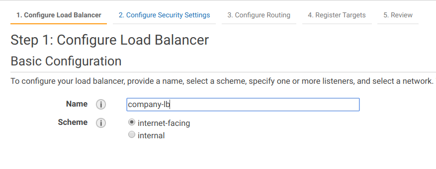
Go to the Configure Load Balancer tab, specify the name for your newly-created load balancer, and select the addressing scheme: internet-facing or internal.
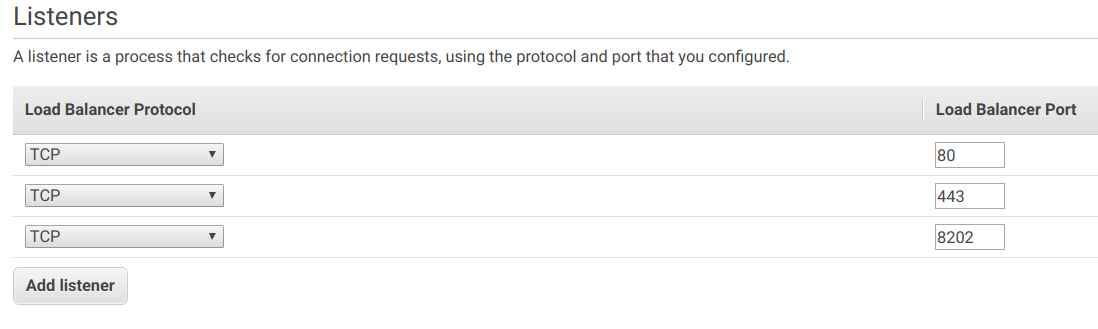
Create one listener for each port, which will accept connections.
A listener is a process that checks for connection requests.
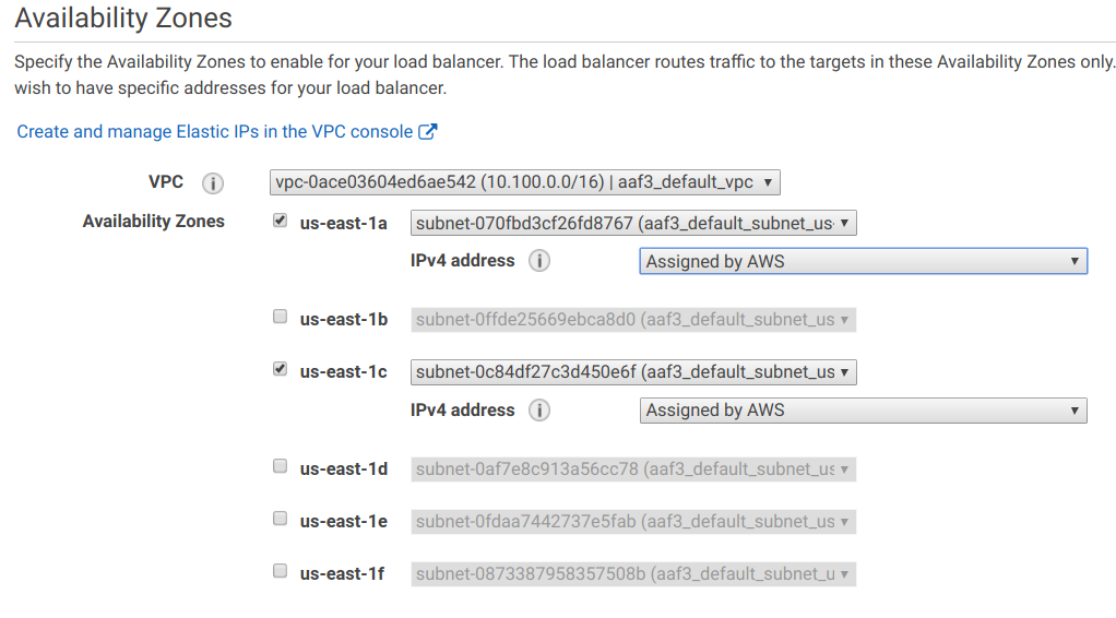
Configure the Network LB to have a separate network interface in both availability zones.
As the high-availability installation requires three Master servers, distribute them among different availability zones (see sample image below).
If you plan to deploy the internet-facing NLB, change the IPv4 address setting for the first subnet to Elastic IP.
Click Next: Configure Security Settings, but skip this section, as you don't have to terminate TLS on this balancer.
Step 5: Configure Routing
Click Next: Configure Routing.
Select Existing target group and choose one of the target groups created in step 1.
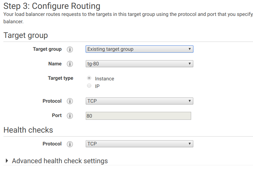
Click Next: Register Targets. You will see the list of instances configured on step 2 as Registered targets.
Click Next: Review, and then click Create.
You have successfully created three target groups and a load balancer with three listeners. Now some additional configuration is required to connect them.
Step 6. Forward ports to corresponding target groups
On the navigation pane, in the Load Balancing section, select Load Balancers and choose the load balancer you have just created.
Go to the Listeners tab. You will see that by default, all ports are routed to the same target group, while the setup requires each port to be forwarded to a corresponding target group:
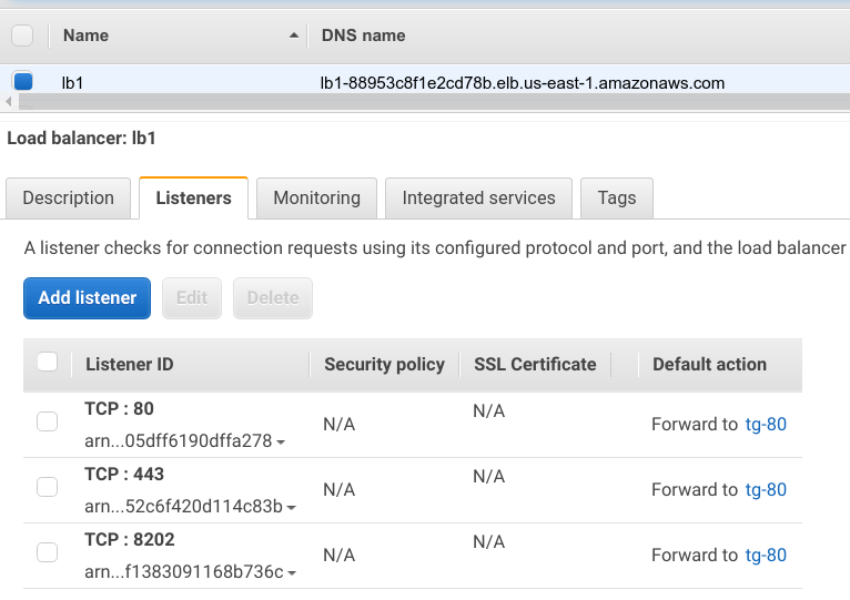
To fix that, click Edit and select a corresponding traffic group for each listener.
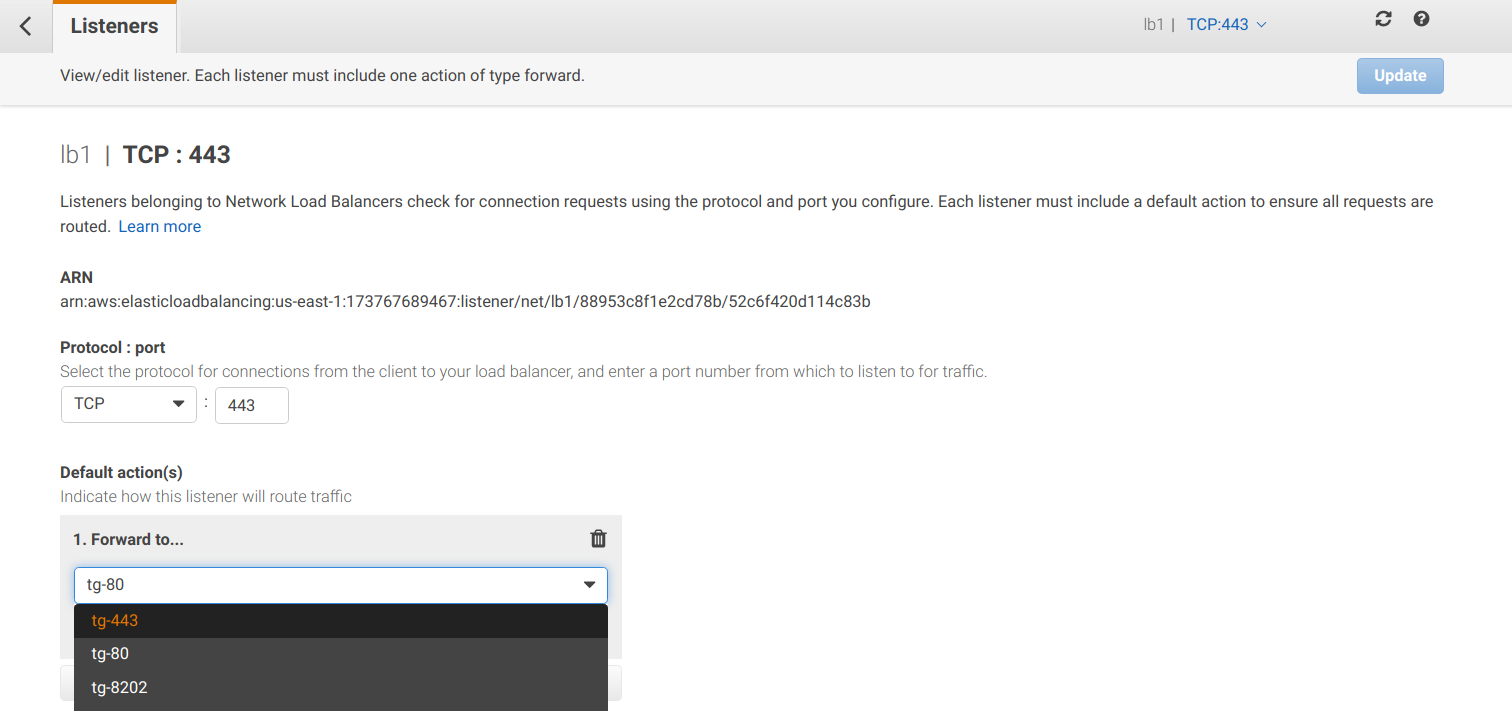
Click Update.
Step 7. Finish routing configuration
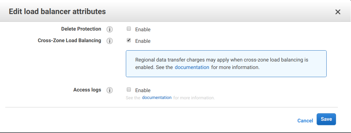
By default, a network load balancer does not route traffic between availability zones. To allow that, you must configure it explicitly; otherwise, the requests can reach only one of the Master servers.
To configure routing:
On the navigation pane, in the Load Balancing section, select Load Balancers and choose the load balancer you have just created.
Go to the Description tab at the bottom, and click Edit attributes.
Select the Cross-Zone Load Balancing checkbox and save your changes:
Note: if you plan to use the Azure external load balancer, follow the requirements from the Hardware load balancer tab. The following instruction applies only to an internal load balancer. But if you plan to use an internal Azure load balancer instead of an external one, then you may face some difficulties, the solution of which is described below.
Before creating a Load Balancer, select a connectivity scheme you are going to use:
Azure internal load balancer is used to balance traffic through MASTER1, MASTER2, and MASTER3 servers. The balancing is performed not directly. There are two additional servers: PROXY1 and PROXY2, which can pass traffic to each of the MASTERs. Thus, Azure internal LB distributes traffic between PROXY1 and PROXY2 servers. See the following diagram:
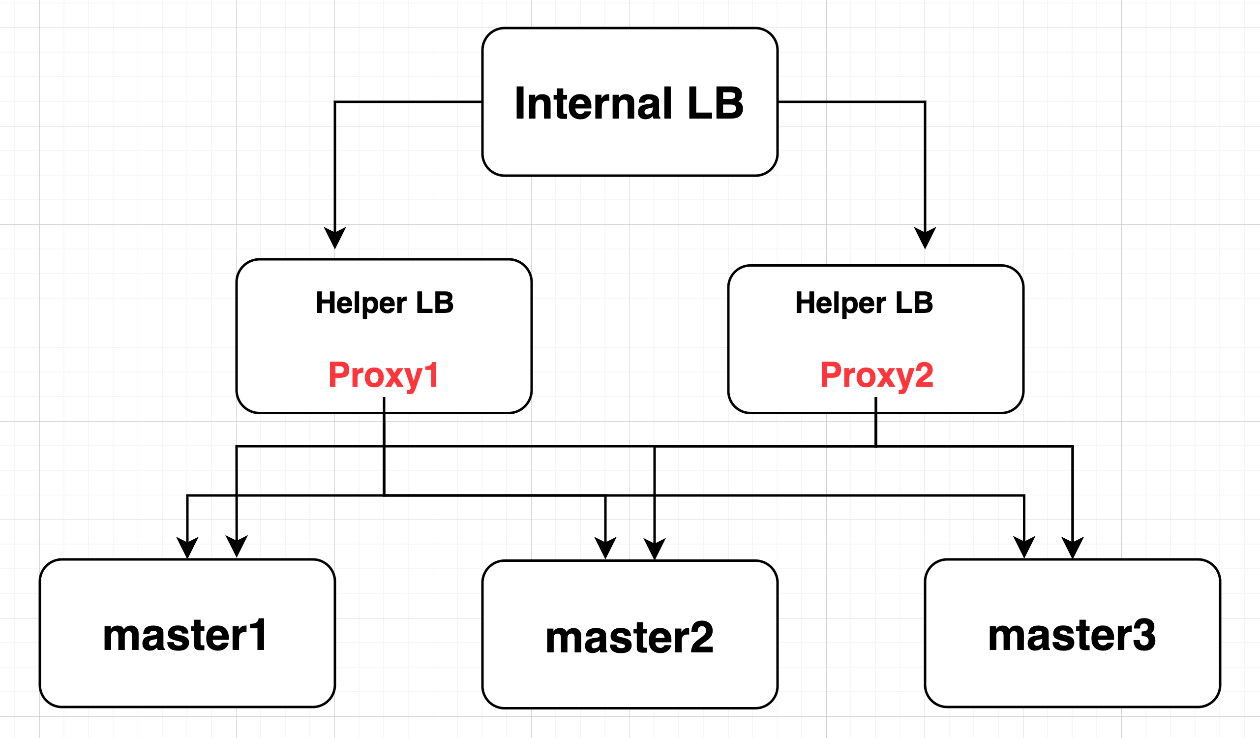
All TCP traffic, which is coming to PROXY1 on ports 80, 443, 8202 and 7374, gets forwarded as-is to MASTER1 or MASTER2 or MASTER3 servers. The same applies to the traffic to PROXY2.
This is done to avoid Internal Azure LB limitations. Requests cannot pass from the backend pool VMs through load-balancer to themselves.
Step 1. Create proxy machines
To comply with HA requirements, you need to have a minimum of two PROXY instances. If one of them is unavailable for some reason, the traffic passes through the second PROXY server.
To create a proxy machine:
Create two virtual machines with CentOS or RHEL operating system in one zone with other Work.AI servers for the HAProxy installation.
Create the directory for the HAProxy binary file and the config file:
# create the directory to place the HAProxy binary and its config file
sudo mkdir -p /opt/workfusion/haproxy-tcp

# change ownership. We're going to run HAProxy as a non-root user (in this case, it is "azureuser")
sudo chown -R azureuser:azureuser /opt/workfusion/
Download the HAProxy binary file from the bucket:
# download HAProxy binary from s3 (link valid till April 29, 2022):
$ cd /opt/workfusion/haproxy-tcp/
$ curl -o 'haproxy' 'https://workfusion-installer.s3.amazonaws.com:443/blobs/binaries/haproxy/haproxy-2.1.4-wf-bundled.bin?AWSAccessKeyId=AKIAIYJMMPKAN2MQSJWA&Expires=1651105799&Signature=fgB9TI9jFQpDnyuSsAZdOnp0r9k%3D'
Add execute permissions to the binary file:
# add execute permissions:
cd /opt/workfusion/haproxy-tcp/
chmod +x haproxy
Allow the HAProxy binary to bind on privileged ports (that are 80/443) when executed by an unprivileged user:
# allow HAProxy binary to bind on privileged ports (that are 80/443) when executed by unprivileged user:
sudo /usr/sbin/setcap CAP_NET_BIND_SERVICE=+eip /opt/workfusion/haproxy-tcp/haproxy
Create the systemd unit file for starting HAProxy when a server is rebooted:
sudo vi /etc/systemd/system/haproxy.serviceThe file must have the following content. Here,
UserandGroupare "azureuser".[Unit]
Description=supervisord
Requires=local-fs.target
After=local-fs.target
[Service]
User=azureuser
Group=azureuser
Type=simple
Restart=on-failure
RestartSec=10
StartLimitInterval=300
StartLimitBurst=5
TimeoutStartSec=300
TimeoutStopSec=30
SendSIGKILL=yes
ExecStart=/bin/bash -c 'exec /opt/workfusion/haproxy-tcp/haproxy -f /opt/workfusion/haproxy-tcp/haproxy.conf'
[Install]
WantedBy=multi-user.targetCreate the HAProxy config file:
vi /opt/workfusion/haproxy-tcp/haproxy.confThe file must have the following content. Remember to substitute the addresses of your Master servers.
global
    log stdout format raw local0

defaults
log   global
mode    tcp
option  dontlognull
timeout connect 5s
timeout check   5s
timeout client  3600s
timeout server  3600s

frontend tcp-proxy
    mode tcp
    log-format  "[%t] [from: %ci] -> [%b] - [HOST:%fp] - [%s:%sp] [%Tt ms]"

    bind *:80
    bind *:443
    bind *:7374
    bind *:8202
    default_backend DEFAULT

backend DEFAULT
mode tcp
        server MASTER1 <master1 internal IP> verify none check port 443 inter 5000 rise 1 fall 1
        server MASTER2 <master2 internal IP> verify none check port 443 inter 5000 rise 1 fall 1
        server MASTER3 <master3 internal IP> verify none check port 443 inter 5000 rise 1 fall 1
Reload the systemctl daemon:
# Reload systemctl daemon
sudo systemctl daemon-reload
Start HAProxy and enable its systemd unit so that it starts on server reboot:
# Start HAProxy and enable its systemd unit to execute it on server reboot
sudo systemctl start haproxy.service
sudo systemctl enable haproxy.service
Repeat these steps for the second Master server.
Step 2. Create internal LB
To create internal LB:
In the Azure WEB console, go to the Load balancing section and click the +Create button.
In the Resource group box, select a group with your resources.

In the Instance details section, specify Name and Region for your balancer, and set Type to
Internaland SKU toStandard.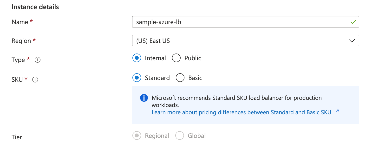
In the Configure virtual network section, in Virtual Network and Subnet, specify your resources. Select
StaticIP address assignment and assign Private IP address. In the Availability zone box, leavezone-redundant.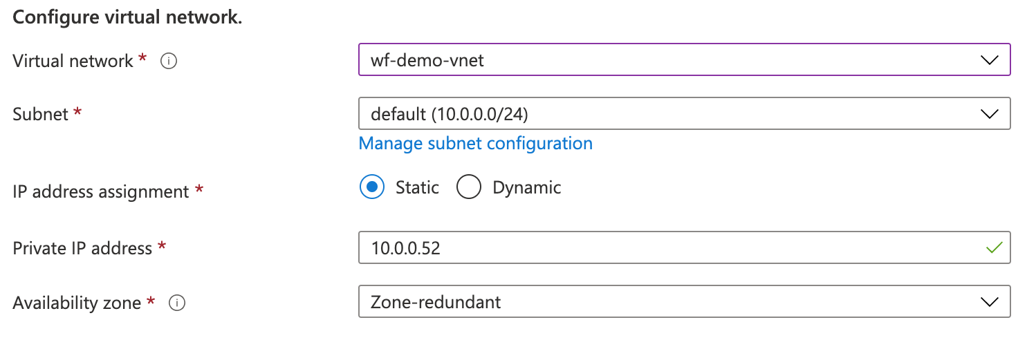
Add some Tag to your LB, if needed.
Select Review + create and Create.
Step 3. Add Backend pools
To add backend pools:
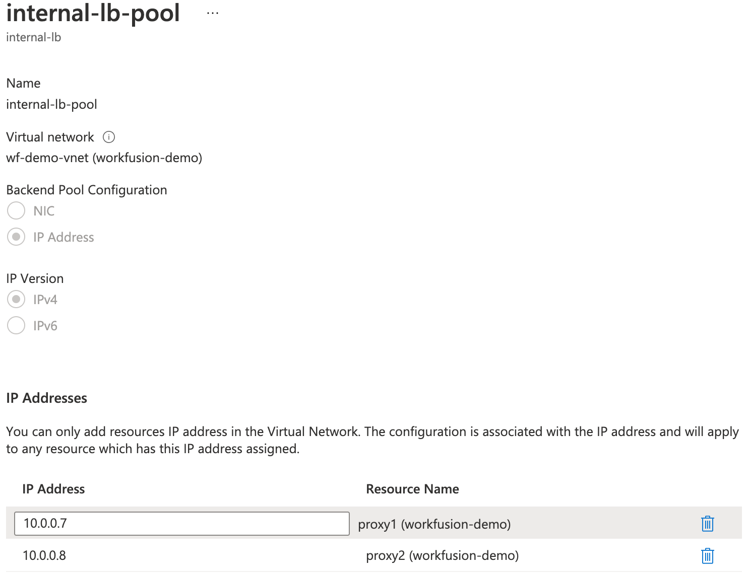
Select your created LB and go to the Backend pools section.
Click +Add and specify Name for your pool.
In Backend Pool Configuration, select
IP Addressand in IP Version, chooseIPv4.In the IP Addresses section, add your proxies:
Step 4. Create Health probe
To create a Health probe:
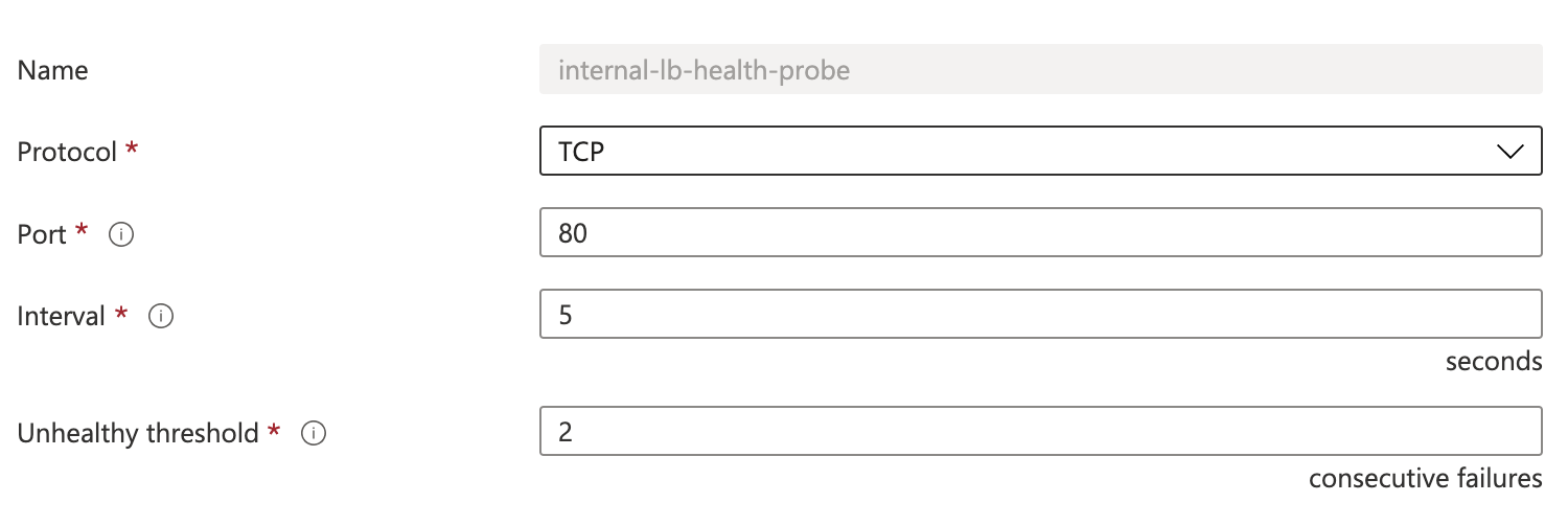
Select your created LB and go to the Health probes section.
Click the +Add button and specify Name for your health probe.
You can leave the default settings:
- Protocol:
TCP - Port:
80 - Interval:
5 - Unhealthy threshold:
2
- Protocol:
Click Add.
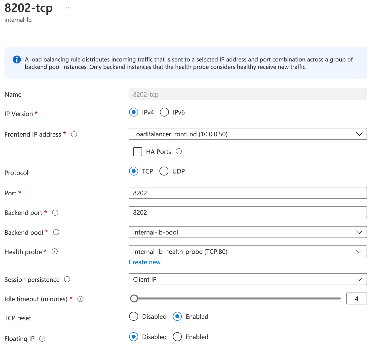
Step 5. Add Load balancing rules
To add the load balancing rules for the example 80 port:
Select your created LB and go to the Load balancing rules section.
Click +Add and specify Name for your load balancing rule.
Specify the following settings:
IP Version:
IPv4Frontend ip address: address of your LB
Protocol:
TCPPort
80Backend port:
80,Backend pool: choose the backend pool that you created earler
Health probe: choose the Health prove that you created earler
Session persistence:
Cluster IPIdle timeout (minutes): leave default— 4 minutes
TCP reset:
EnabledFloating IP:
Disabled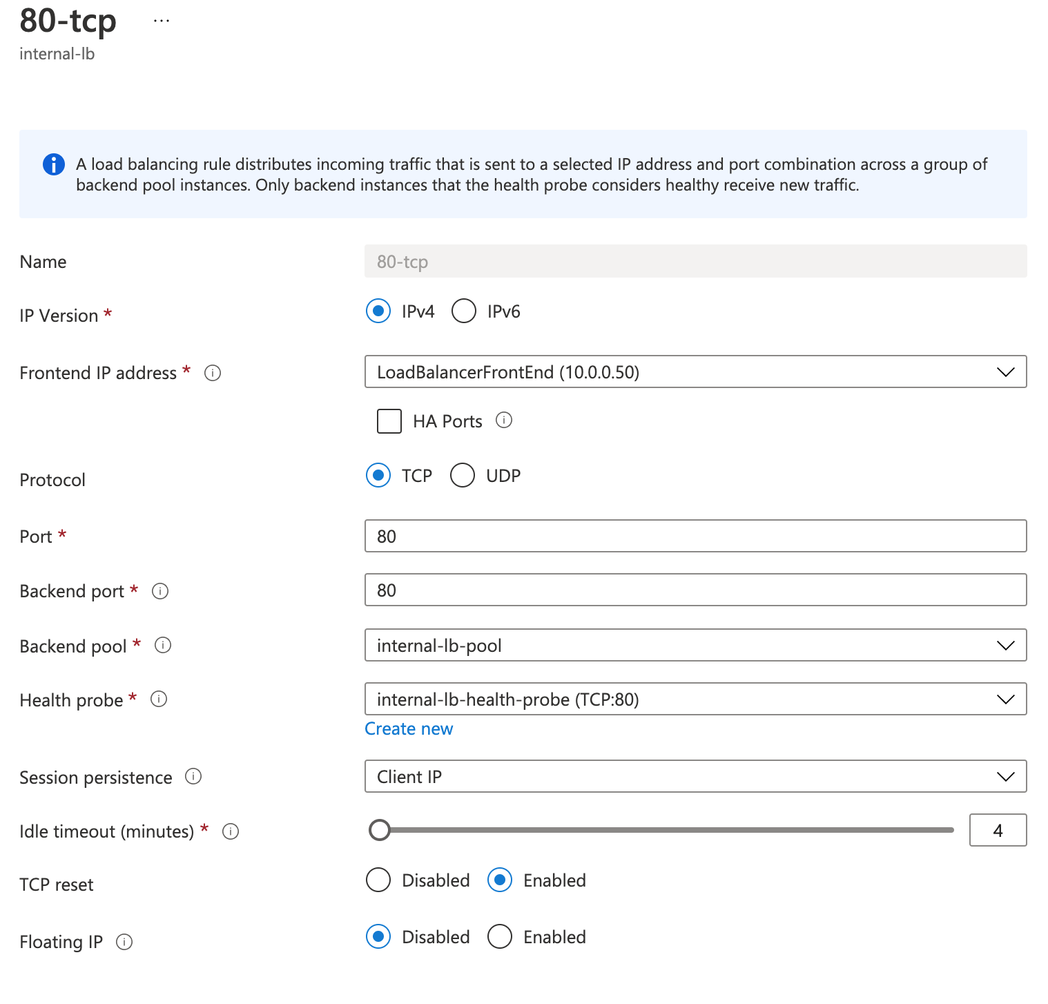
Click Add.
Repeat these steps for ports 443, 7374, and 8202. As a result, you have the following configurations:
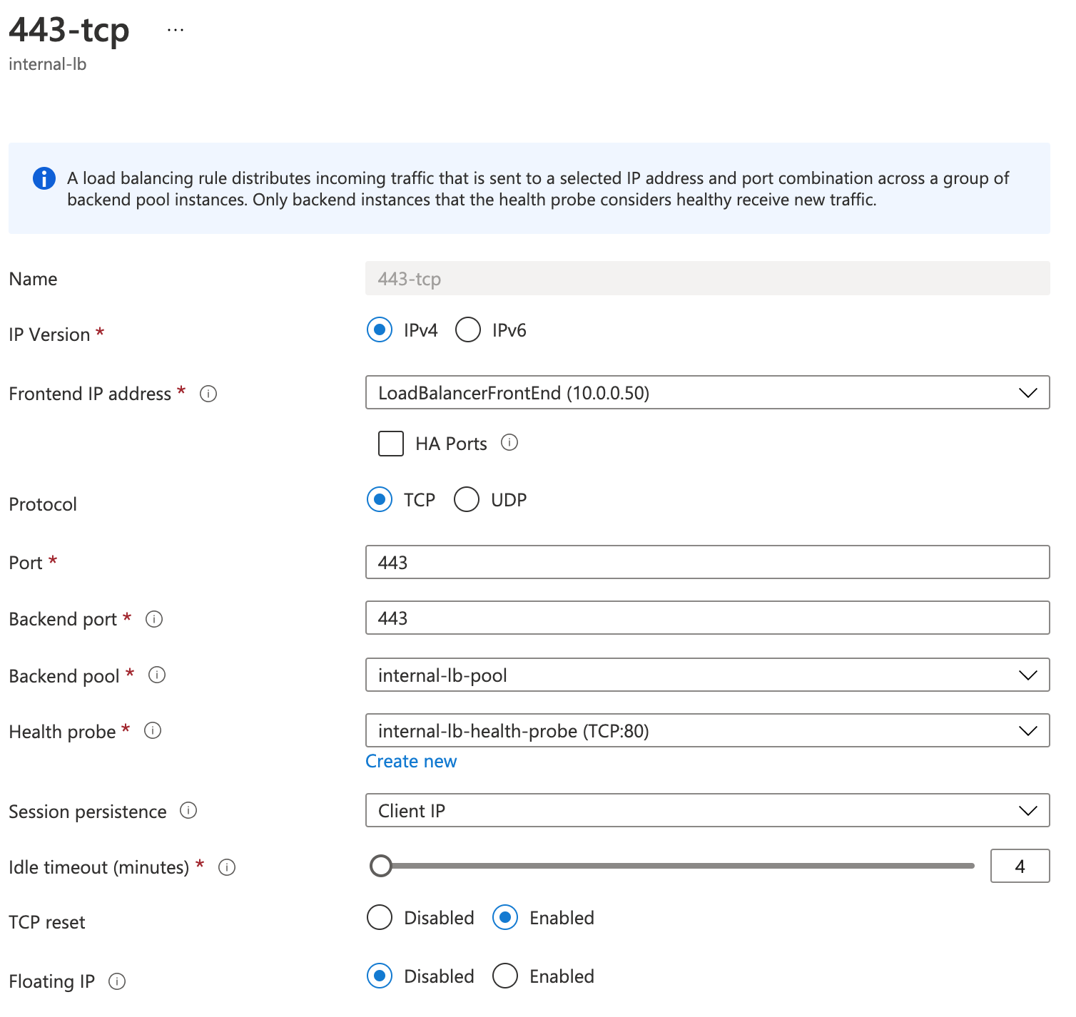
You have successfully created three rules in your LB:
