
Load balancer
Requirements
note
You only have to configure a load balancer if you are planning to set up IA Cloud Enterprise in the high-availability mode. In the case of the Basic installation, ignore this instruction.
A hardware load balancer must be provided and configured in advance before the installation of Enterprise Edition.
The load balancer must have an IP address (Virtual IP, VIP) assigned to which all clients' external connections will be established.
The load balancer must support Layer 4 TCP load balancing.
The load balancer must listen to the specific ports described in the table below. Port numbers can be overridden in the config file before the installation. The table describes default values of port numbers set initially in the config file inside the installation package. If you want to use different ports, make sure that the ports configured to listen on load balancer are updated accordingly in the configuration file during installation:
Port numbers (default values from config.yml) Respective setting in config.yml TCP: 80 lb_port TCP: 443 lb_port_ssl TCP: 8202 vault_port The load balancer must be configured to route all TCP traffic from the specified ports to the same ports on APP1 and APP2 servers (simple round-robin balancing between APP1 and APP2). It means that the ports must be accessible from load balancer's network interface to APP1 and APP2 servers' network interfaces.
We recommend configuring the load balancer to perform TCP health-checks of the "
lb_port_ssl" port of APP1 and APP2 servers every 5 seconds to check that a server is alive.All load balancer TCP ports from the table above must be accessible over the VIP from every server of the environment.
TLS termination must be disabled on the external load balancer.
How to configure a load balancer
In the load balancer's configuration, specify the following parameters for it:
Configure the list of servers to be balanced:
- APP Server hostname 01 (for example, host-ct1.example.com)
- APP Server hostname 02 (for example, host-ct2.example.com)
Create the following list of ports that VIP will listen to (see comment and table above, that these ports may be changed during installation):
- TCP: 80
- TCP: 443
- TCP: 8202
Configure health checks:
- Ports to listen: TCP 443. If the port is unavailable, HAProxy is down.
- Servers in the Target group to check: APP Server hostname 01, APP Server hostname 02.
- Rules:
- The number of failed health checks to consider the server is down. By default, 3.
- The number of passed checks to consider the server is restored. By default, 1.
- The interval of health checks, by default, 20 seconds.
Set Sticky sessions to the Round Robin mode.
Set Client NAT.
Before creating a Load Balancer, make sure that you understand, which connectivity scheme you are going to use:
- Internet-facing: a public IP address is assigned to the customer-facing interface of the balancer. In this case, before creating a load balancer, make sure that you have a free Elastic IP (EIP) address available.
- Internal: a private IP address is assigned to the customer-facing interface of the balancer.
Step 1. Create target groups
A target group is a set of backend servers. In our case, they are two application servers.
Go to https://console.aws.amazon.com/ec2/ to open the Amazon EC2 console.
On the navigation pane, in the Load Balancing section, select Target Groups.
Select Create target group.
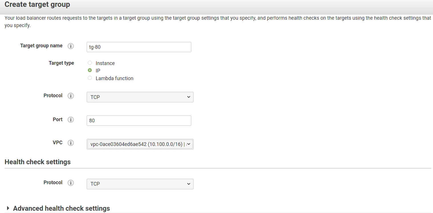
Create three target groups one by one for each port that Load Balancer is going to listen to. Specify the following parameters:
- Target group name: any meaningful string.
- Target type: IP.
- Protocol (for the target group and health-checks): TCP.
- Advanced health check settings: we recommend to leave the settings in this section as is.
Here is an example for port 80:
Step 2. Register targets with target groups
For each of created target group do the following:
Go to the Targets tab and click Edit.
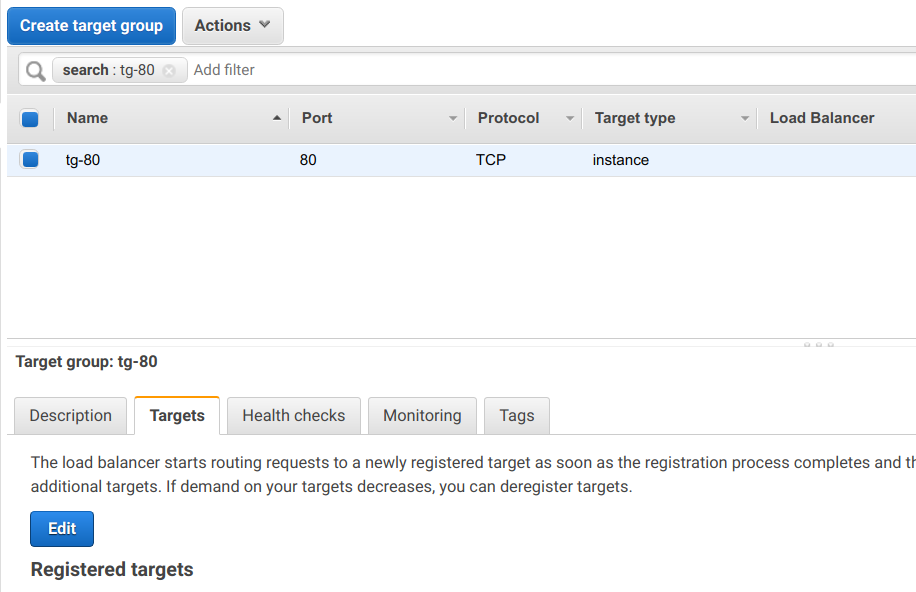
Select the "+" tab at the bottom of the page, fill in IP of each of two application servers and click "Add to list". Then, click the "Register" button. As a result, you will see two servers on the Targets tab at the top of the page:
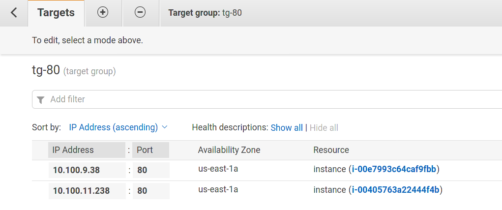
Click Save.
Step 3: Create a Network Load Balancer and a Listener
- On the navigation pane of the AWS console, in the Load Balancing section, select Load Balancers.
- Select Create Load Balancer.
- For Network Load Balancer, select Create.
Step 4: Configure a Network Load Balancer (NLB)
To create listeners and specify availability zones:
Go to the Configure Load Balancer tab, specify the name for your newly-created load balancer, and select the addressing scheme: internet-facing or internal.
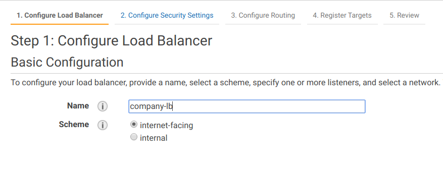
Create one listener for each port, which will accept connections.
A listener is a process that checks for connection requests.
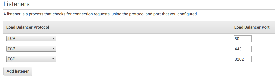
Configure the Network LB to have a separate network interface in both availability zones.
As the high-availability installation requires two APP servers, distribute them among different availability zones. The image below shows that The APP servers are running in the "a" and "c" availability zones.
If you plan to deploy the internet-facing NLB, change the IPv4 address setting for the first subnet to Elastic IP.
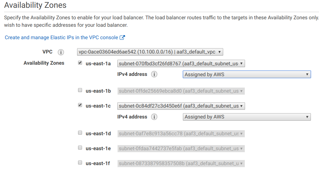
Click Next: Configure Security Settings, but skip this section, as you don't have to terminate TLS on this balancer.
Step 5: Configure Routing
Click Next: Configure Routing.
Select Existing target group and choose one of the target groups created on step 1.
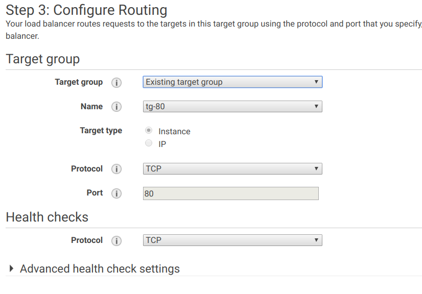
Click Next: Register Targets. You will see the list of instances, configured on step 2 as Registered targets.
Click Next: Review, and then click Create.
You have successfully created three target groups and a load balancer with three listeners. Now some additional configuration is required to connect them.
Step 6. Forward ports to corresponding target groups
On the navigation pane, in the Load Balancing section, select Load Balancers and choose the load balancer that you have just created.
Go to the Listeners tab. You will see that by default all ports are routed to the same target group, while the setup requires each port to be forwarded to a corresponding target group:
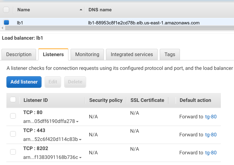
To fix that, click Edit, and select a corresponding traffic group for each listener.
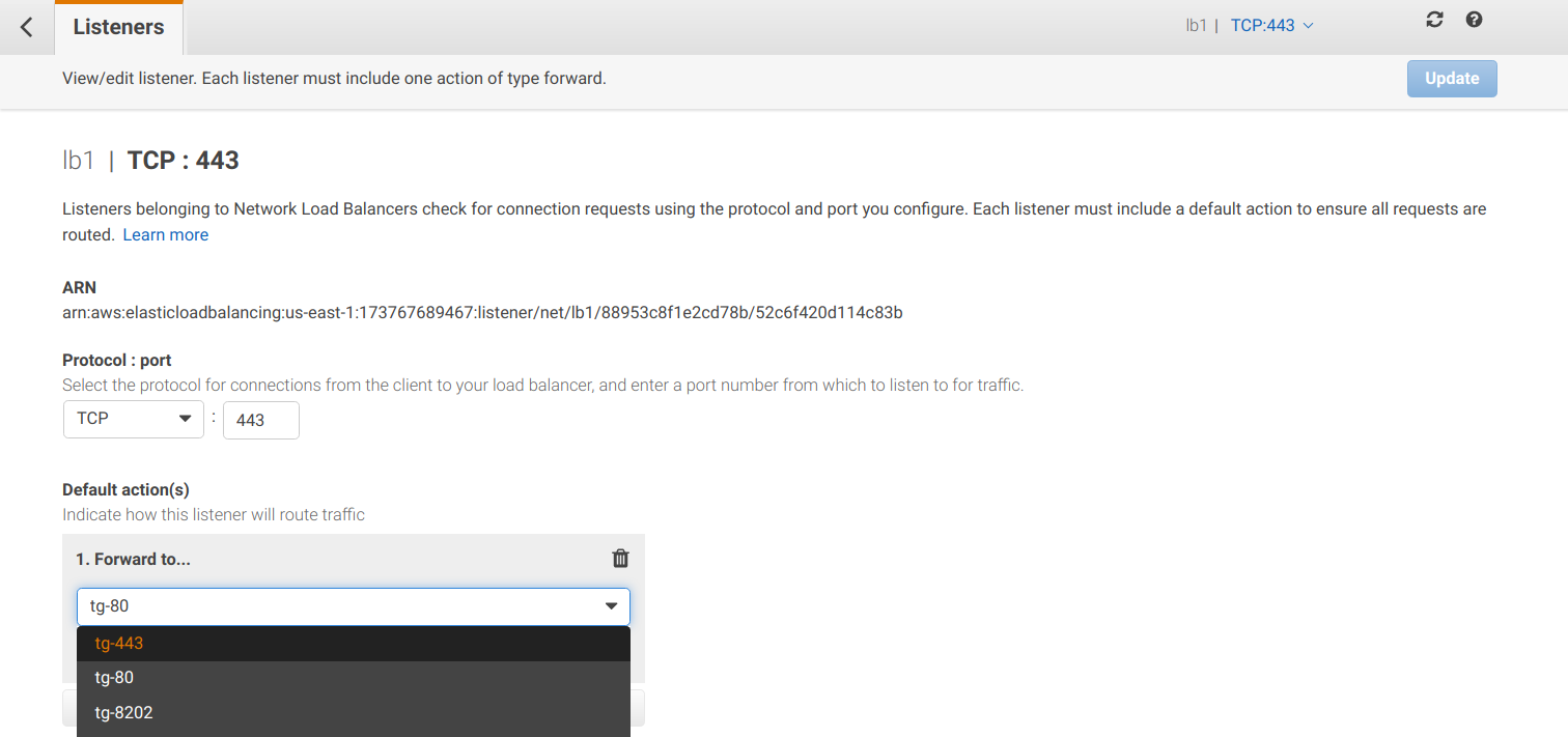
Click Update.
Step 7. Finish routing configuration
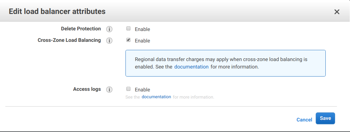
By default, a network load balancer does not route traffic between availability zones. To allow that, you must configure it explicitly; otherwise, the requests can reach only one of the APP servers.
To configure routing:
On the navigation pane, in the Load Balancing section, select Load Balancers and choose the load balancer that you have just created.
Go to the Description tab at the bottom, and click Edit attributes.
Select the Cross-Zone Load Balancing checkbox and save your changes:
Checklist
To facilitate preparation for the IA Cloud setup, after you configure the load balancer, complete the checklist, and provide it to the WorkFusion deployment engineers.
Click the link to download the archive with all checklists.